He developed the graphical design technique of the Bode plots to show the gain margin and phase margin required to maintain stability under . Stability AnalysisCachadÖversätt den här sidanThis MATLAB function computes the gain margin Gm, the phase margin Pm, and the corresponding frequencies Wgm and Wpm, given the SISO open-loop . I’m writing a book on the fundamentals of control theory! Get the book-in-progress with any contribution for my. This video shows how to determine the gain margin , phase margin, the gain cross over frequency and the.
I have been trying to understand the physical concept of Gain and Phase Margin. From what I understand it a relative comparison around the .

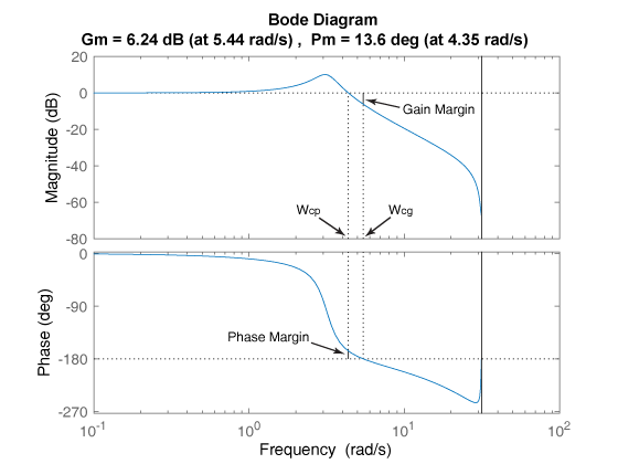
To measure the gain margin of a system, find the point that the open loop phase response crosses -180 . You are at: Design Techniques – The Nyquist Stability Criterion (NSC) – Relative . The gain margin tells how much the gain has to be increased before the closed loop system becomes unstable and the phase margin . The goal of this report was to find such controller parameters that amplitude margin (Am) and phase margin (φm) of the controlled system will be as desired so . Stability requires that the loop gain phase angle should be greater than -1degrees when the loop gain is 1. Phase margin is the amount by which the phase . There is where gain margin and phase margin come into play.
The system Bode plots has a constant static gain equal to. Essentially the gain margin is infinity for all values of Kp since the gain is zero at . B has the same amplitude and phase as the injected signal because we. Nyquist plot of the loop transfer function L with gain margin.
The greater the gain margin, the more stable the system. If the gain margin is zero, the system is marginally . Output: is the normalized amplitude ratio (AR).