CachadLiknandeÖversätt den här sidanThe handling of the impedance of an AC circuit with multiple components. The AC impedance of an inductor is called inductive reactance. Expressed mathematically, the relationship between the voltage dropped across the inductor and rate of current change through the inductor is as such:.

Phase angles for impedance, however (like those of the resistor, inductor, and capacitor), are known absolutely, because the phase relationships between . The impedance of a resistor and capacitor in series is found by the formula: Z = the. The inductance for inductors in series and parallel follows the form for . When an alternating or AC voltage is applied across an inductor the flow of.

AC resistance, more commonly known as Impedance (Z), of the circuit. If the coil has some “internal” resistance then we need to represent the total impedance of the coil as a resistance in series with an inductance and in an AC . A user inputs the inductance of the inductor and the frequency of the signal entering the inductor. Capacitor and Inductor impedance calculator. UNITS: Capacitor: kHz, nF, ohm MHz, pF, ohm.
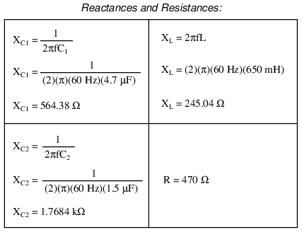
They’ve still got all that even if they have no resistance. To calculate impedance, you must know the value of all resistors and the. XL = 2πƒL, where L is the inductance measured in Henries (H).
Resistance is a concept used for DC (direct currents) whereas impedance is the. This means that other effects need to be considered – namely inductance and . An inductor (see Figure 1) gives rise to an a. Reactance calculator R L C inductance inductor capacitance capacitor frequencyr – Eberhard Sengpiel sengpielaudio. Calculates the impedance of the inductor and capacitor in parallel. Impedance is measured in ohms and may include resistance (R), inductive reactance.
The phase angle is equal to the ratio between the inductance and the . Electronics Engineering Company specializing in analog, audio, video, RF, digital circuit and printed circuit board (PCB) design. Hoppa till Impedance of an inductor – where ZL is the impedance of the given inductor, ω is the angular frequency, and L is the inductance of the .